Локальная версия помершего сайта - http://www.chuntey.com/speccybob/
SpeccyBob Lite
SpeccyBob is a computer that you can build yourself from readily available parts. It is compatible with the Sinclair ZX Spectrum of the 1980's. There are two versions of SpeccyBob:
SpeccyBob Lite is basically just a clone of the Sinclair ZX Spectrum. Currently, this is the version that I am working on before adding the extra features of SpeccyBob. Alas, I had virtually completed the design until the great disk crash of 2001 came along. so here goes again from the beginning.
SpeccBob 2, while maintaining compatibility with the original Spectrum, adds and improves to the design. Features include selection video modes, IDE interface, and up to 4Mb RAM etc.
SpeccyBob Lite Description
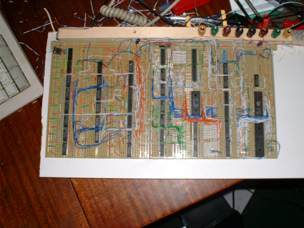
UPDATE: I've corrected a mistake in the download file that showed the the wrong image for the bottom side of the video board. Sorry. SpeccyBob Lite is a faithful clone of the 48K Spectrum. It is 99% Compatible, yet achieves this without using any custom parts. If fact, it is build entirely around standard 74HC series logic chips. The only programmable device in the circuit is the EPROM. Even then, you can drop in the ROM from a dead Spectrum. Click on the links on the left for the circuit diagrams and a description of how it works. There are also links for some pictures of the prototype, and a download of all the diagrams/PCB layout in postscript format.
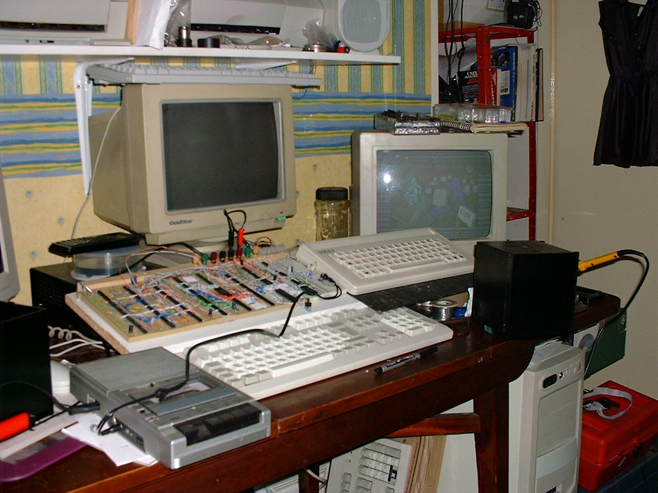
Pictures of SpeccyBob Lite Running
|
The basic system - only 16K of RAM |
A Complete 48K system including tape interface |
|
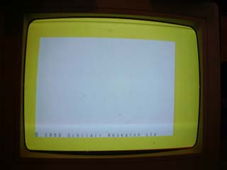
My first attempt at switching it on - I'd gotten the address lines mixed up. |
Soon Sorted that out though. |
|
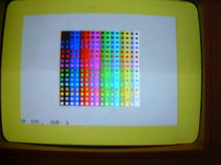
SpeccyBob running in true 64 column mode - 512x192 pixels. |
SpeccyBob running with separate Bright controls for both Ink and Paper. |
|
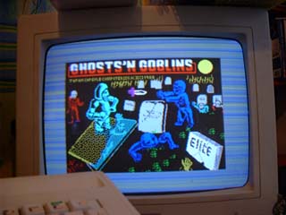
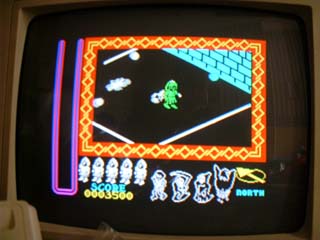
Loading the game "Ghosts 'n Goblins" |
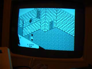
SpeccyBob running the game "Fairlight" - Note: no dot crawl :-) |
|
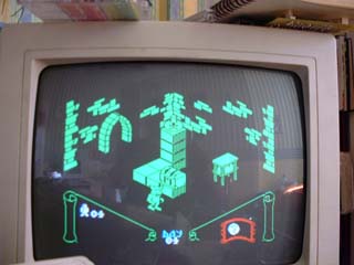
KnightLore |
NightShade |
|
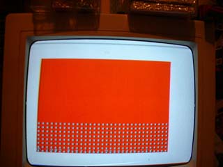
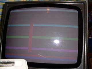
Horizontal Bars (Sorry about the flash but my camera used too slow a exposure time without it) |
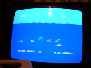
Aquaplane - multicolour border
|
|
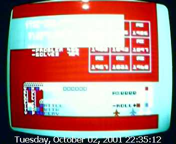
FullScreen Characters in Starion. I had to use the Webcam to grab this one as the Digital Camera was too slow again. |
|

SpeccyBob Lite Clock Circuit
OK, I hope someone can understand this...
U7C,D & E along with the crystal form a 14Mhz clock which is divided by 2, then by 2 again by U13 to create the 7Mhz and 3.5Mhz clocks.
U1,2 & 3 (4 bit synchronous counters) are clocked at 7MHz. U8 along with U12a detect when the counter has counted to 448 and reset, thus forming a modulo-448 counter. This forms the length of the horizontal scanline (448 is 224 T-states * 2 because the counter is clocked at 7MHz, not 3.5).
H7 from this counter is used as an active low Horizontal display enable (Low for the first 256 counts, then high).
U9 & U10 pick out the start and end of the Horizontal Sync pulse which gets latched by U15B.
U4, 5 & 6 form the vertical counter. They are clocked by H7 of the horizontal counter so that they count scanlines. U11 with U12C reset the counter when it reached 312 so that 312 scanlines are produced on the monitor.
U14A latches the Vertical Sync pulse. It is cleared whenever the vertical counter is reset, then set again at the end of the first line (R0 goes high).
U14B signals the end of the top border. Like the Vertical sync pulse it is cleared then the counter is reset, but sets on R6 (line 64).
U15A marks the start of the bottom border. It is reset on with the counter and set with R8 (line 256). The area between line 64 and 256 marks the displayable area.
The above 2 signals, along with the horizontal video enable are then NOR'd together to produce the Video Enable line.
The clock board is also responsible for synchronising the activities of the video board. To do this, as well as using VE (Video Enable), it can send 5 signals to the video circuitry: S0, S1, S2, Vacc & Cacc.
These signals are derrived from the Horizontal counter by U16 (a 3 to 8 line decoder). S0 tells the video circuit to load the attribute byte from RAM. S1 signifies that the bitmap should be loaded from RAM, and also starts the output of a new byte. S2 tells the video board to increment its address counter.
Vacc and Cacc are responsible for deciding whether the CPU or video circuitry have access to Video RAM. Vacc is active on states S0 & S1, Cacc at all other times.
U16 along with U18 also control contended RAM timing. If IOCS (a ULA IO access) or VRAM (A video RAM access) is enabled, the Z80 is paused 'till it is allowed access again.
Finally, U17 delays the Video Enable line to the video board until after the the first attribute is fetched from RAM and the bitmap is ready to be displayed.
SpeccyBob Lite Video Circuit
SpeccyBob Lite is a faithful clone of the 48K Spectrum. It is 99% Compatible, yet achieves this without using any custom parts. If fact, it is build entirely around standard 74HC series logic chips. The only programmable device in the circuit is the EPROM. Even then, you can drop in the ROM from a dead Spectrum.
Click on the links on the left for the circuit diagrams and a description of how it works. There are also links for some pictures of the prototype, and a download of all the diagrams/PCB layout in postscript format.
SpeccyBob Lite CPU Circuit
This will be populated soon.
SpeccyBob Lite Downloads
Download all the circuit diagrams along with PCB Layouts here.
To use SpeccyBob, you'll also need a 16k ROM image. I suggest you either use a real Spectrum ROM, or visit the links page and use an image from one of the many Spectrum emulators. Remember though SpeccyBob Lite only emulates a 48K Spectrum, so don't try using the 128K/+2/+3 ROMs with it.